When you visit any website, it may store or retrieve information on your browser, mostly in the form of cookies. This information might be about you, your preferences or your device and is mostly used to make the site work as you expect it to. The information does not usually directly identify you, but it can give you a more personalized web experience.
Because we respect your right to privacy, you can choose not to allow some types of cookies. However, blocking some types of cookies may impact your experience of the site and the services we are able to offer.
You Allow:
Strictly Necessary Cookies(Required)
These cookies are necessary for you to browse our website and use its fundamental services,and they don't require your consent.These cookies allow us to offer you the essential functions of the website(account access,language used,order played,payment etc),and can also be used for identity verification and security.If you disable them,we will not able to fulfill your basic request.
These cookies collect anonymous information on your online operation behaviors that help us improve website construction. If you reject these cookies, you may not be able to use certain features of our websites and services.
These cookies allow us to remember the choices you have made about your preferences, such as what language you prefer. If you reject these cookies, you may feel that the efficiency of browsing the web has decreased.
These cookies carry out personalized activities to advertise products and services which you are interested. If you reject these cookies, you will still see advertisements that are not much relevant to your interest or demand.
 mk_glover
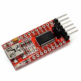

mk_glover The board is self explanatory and is designed to be powered from the USB interface. It uses an FTDI FT232RL USB to UART chip with TTL levels on the serial interface. The datasheet for the chip is is available on the FTDI website.:- DS_FT232R.pdf. However, the board and chip does support being powered by a +3.3V to +5.25V supply on the "5V" hole for the device core. This is the Vcc pin of the chip. Now, the hole labelled "VCC" is connected to the VCCIO pin of the FTDI device and in the words of FTDI:- "+1.8V to +5.25V supply to the UART Interface and CBUS group pins (1...3, 5, 6, 9...14, 22, 23). In USB bus powered designs connect this pin to 3V3OUT pin to drive out at +3.3V levels, or connect to VCC to drive out at 5V CMOS level. This pin can also be supplied with an external +1.8V to +2.8V supply in order to drive outputs at lower levels. It should be noted that in this case this supply should originate from the same source as the supply to VCC. This means that in bus powered designs a regulator which is supplied by the +5V on the USB bus should be used." Care may be required for supply isolation in your application.
Helpful (0)