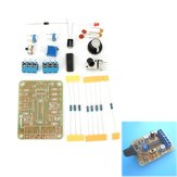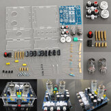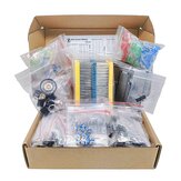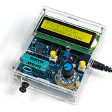
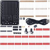
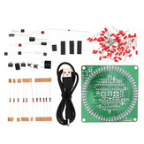
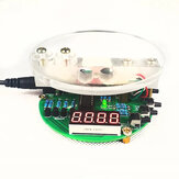
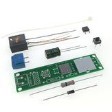
Geekcreit® XR2206 Function Signal Generator DIY Kit Sine Triangle Square Output 1HZ-1MHZ
US$3.54
A part of the review has been auto-translated.

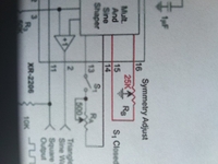
It has some issues and it is not perfect, it has a DC offset at the output and it has very low power output capabilities. The output impedance is too high to power anything but as a basic low power signal source it is fine. I highly suggest building a current or power amplifier to go along side it to get more power. For the price it is a really good learning tool if you have an oscilloscope and since you are adjusting the function gen blindly without a scope it is not that useful. You could even use your phone for a function gen but this does have the advantage of better frequency range and probablyt better rise/fall times making it fast. It has its place but it is not a precision intrsument, just a hobby learning tool, try to use a capacitor in series at the output to remove the offset
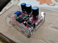

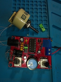
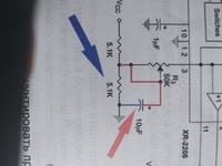
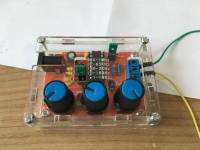
PB is good quality and there is no major problem mouting it Some gotchas : * The square output is not modulated by the amplitude pot, it will always be maximum. I searched a long time for that. * The bolts are BELOW the pcb, that's why the internal screws look too short. They are just there for alignment, The PCB is hold back by the pots being sandwitched by the case (see pics, i used nylon screws but they are ~ same size as the provided ones) * you can add a led + ~ 1k resistor a tthe top of R3/R5 (R3 is VCC, R5 is GND) * The pots are not all the same, one is 100k, the 2 others are 50k


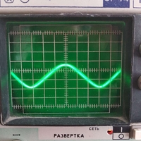
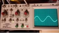
Nice set. Collected - earned. There's a lot written on the Internet how to adjust and improve. After finishing it got a clean sinus. After refinement, it can turn out a pretty decent amateur universal generator.
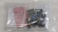
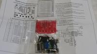
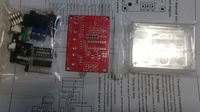
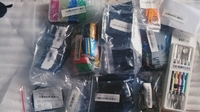
Great purchases, order placed and delivered 15 days later at the Post Office, congratulations to the BG team for the good work. It arrived in a simple package with padding protecting some assorted items, and in perfect condition. After opening and photography, it touch me a lot of small items in one purchase and I did not have much time available, however, I did some tests and observations. A good DIY Kit, the components are in separate packaging, it sees to be ready to be assembled without having to buy extra parts on the market or search for diagrams on the internet and print. I liked it and will be assembly soon, as soon as I have time available. Great acquisitions, request made and delivered 15 days later at the Post Office, compliments to the BG team for the good work. It arrived in a simple packaging with padded protecting some assorted items, and in perfect condition. After opening and photographing, it took me as it was a lot of small items in a purchase and I didn't have much time available, however, I did some tests and observations. A good DIY Kit, the components are in separate packaging, seems to be ready to be assembled without having to buy extra parts on the market or fetch scams on the internet and print. I enjoyed it and will be riding soon as I have time available.
Pont úgy jött meg, ahogy ígérték egy hét alatt itt volt. Ennyi pénzért a hülyének is megéri, hát még nekem. Összerakni egyszerű mint a faék. Játéknak meg jobb mint a LEGO. A tápegység nem tartozék.


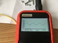
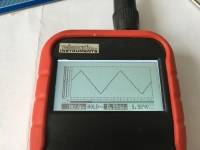
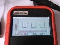
Assembly is really easy and done within 15 minutes. Waveform output of square and triangle work fine, sine wave is more tricky. Supply voltage should be 12...12.5 V. Not all frequencies are stable and only a range of the amplitude yields an undistorted sine wave. Keeping this in mind, it works quite well and is nice for quick demonstrations or to put it in your pocket.
fast shiping and product work well
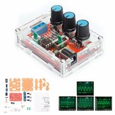
...has arrived this morning and, in evening, has taken forms! as it's seen by the photos.


Great piece of kit. Very usefull for beginners. Reasonably accurate at low frequencies. The assembly is simple and funny. Highly recommended!


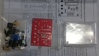
Short notice in English language. Very easy to assemble. See the pictures for reference. The height of the box is quite limited, maintain the capacitors as close as possible to he PCB else you will be unable to close the box. Also, the power socket (JK1) and the variable resistors R2, R7 and R8 emerge too much below the PCB, and you must cut a small part of their pins. For the variable resistors and the 2 sockets JK1 and P1, as much as possible use a larger tip on your iron solder or raise the temperature by 10 to 15 degrees Celsius because of their thermal mass. Place the jumpers for the frequency range and the signal type as needed. Powered and worked fine.


Geekcreit® DIY Mini Tesla Coil Module Unassembled 15W DC 15-24V 2A Plasma Speaker Electronic Kit
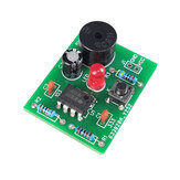
Geekcreit® DIY Shaking LED Dice Kit With Small Vibration Motor

DC5V-9V LED Chaserr DIY Kit LED Tracking Light DIY Parts Electronic Production Kit
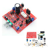
0-30V 2mA - 3A Adjustable DC Regulated Power Supply Module DIY Kit
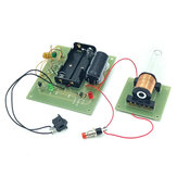
Electromagnetic Gun DIY Kit Electromagnetic Experiment Equipment
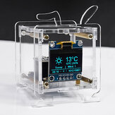
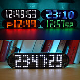
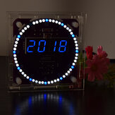
Geekcreit® DS3231 High Accuracy Multifunction LED Dot Matrix Animation Effects Clock DIY Kit

Geekcreit® XR2206 Function Signal Generator DIY Kit Sine Triangle Square Output 1HZ-1MHZ
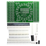
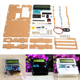
5Pcs DIY SMD Rotating LED SMD Components Soldering Practice Board Skill Training Kit
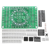
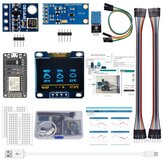
DIY LED Digital Watch Electronic Clock Kit With Transparent Cover

EQKIT CNC Regulated Power Supply Kit Adjustable with Voltage Indication Electronic DIY Production


10Pcs DIY SMD Rotating LED SMD Components Soldering Practice Board Skill Training Kit
Electronic Circuit DIY Production Analog Telegraph DIY Spare Parts Welding Training DIY Kit
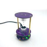
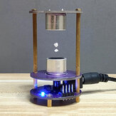
DC12V DIY Electronics Kit Ultrasonic Suspension Standing Wave Controller Diy Welding Kit

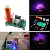
3pcs DIY Mini Tesla Coil Module Unassembled 15W DC 15-24V 2A Plasma Speaker Electronic Kit
Geekcreit MB-102 MB102 Solderless Breadboard + Power Supply + Jumper Cable Kits
EQKIT® DIY Light Operated Switch Kit Light Control Switch Module Board With Photosensitive DC 5-6V
EQKIT® 60 Seconds Electronic Timer Kit DIY Parts Soldering Practice Board
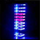
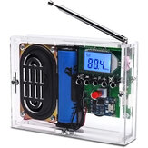
DIY Dream Crystal Electronic Column Light Cube LED Music Voice Spectrum Kit
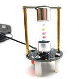
DIY Ultrasonic Suspension Learning Kit Mini Levitator Set 12V Not Assembly
DIY 51 Single Chip Microcomputer Electronic Scale Production Kit
Geekcreit® DIY Mini Tesla Coil Module Unassembled 15W DC 15-24V 2A Plasma Speaker Electronic Kit

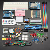
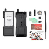
UNOR3 Development Board 830-hole Breadboard Improved Learning Starter Kit or DIY Robot Programming

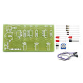
5Pcs Original Hiland 0-30V 2mA - 3A Adjustable DC Regulated Power Supply DIY Kit
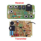
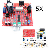
DIY Electronic Walkie-talkie Production Kit Starter Kits Welding Experiment Training Kit

830-hole Breadboard for UN0 R3 Starter Kit with Mainboard DIY Electronic Kits

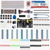
TJ0161 400-hole Starter Kit Resistor LED Capacitor Jumper Wires Breadboard Resistor Kit for UNOR3
Starter Kit for UN0 R3 Beginner 13 in 1 Starter Kit Mini Breadboard LED Light Jumper Wire Button
EQKIT® Arc Ignition Lighter DC3-5V 3A DIY High Pressure Electronic Lighter Module Kit