US$11.99
Klantbeoordelingen
- Alle beoordelingen(16)
- Afbeeldingen
- Videos
Sorteren op:
Recensies alleen uit uw land (United States)
|
Toon origineel
Een deel van de recensie is automatisch vertaald.
-
 14/09/2022
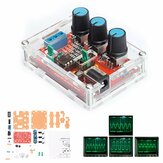
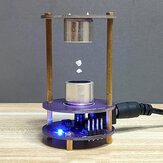
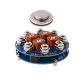
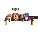
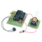
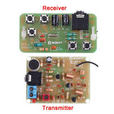
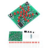
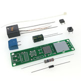
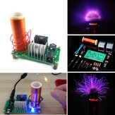
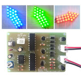
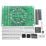
The electronics of the GY20451 The version of the GY20451 supplied to us contains only ten electronic parts. Thus, the scheme is quickly reconstructed and worked out in the illustration below. The 12 V supply voltage is converted into 5 Vdc in U1, an AMS1117, to power the microcontroller. Both the input and output of this stabilizer are decoupled with capacitors C5, C1 and C2. LED1 is connected to the 5 V output via the series resistor R1. An STC15W104 is used as microcontroller. It has a built-in clock generator, so no external parts are necessary in this scheme. Two square waves with a frequency of 40 kHz appear at the outputs P3.2 and P3.3. These two signals drive the two inputs of U3, a TCA4427. That is a double 'High-speed Power MOSFET Driver'. The outputs are connected by means of two MOSFETs either to ground or to the 12 V power supply. These two outputs directly feed the two piezoceramic resonators TX1 and TX2.
Reacties (5)Toon origineel -
 BemindeVIP3BE19/09/2022
very nice project to solder and study! very educational!
ReactiesToon origineel

Show:
Wellicht ben je ook geïnteresseerd in
-
 US$37.99
 -
US$2.99
-
US$59.99
-
US$30.99
Geekcreit® DIY Imiteren Glow Klokset Volledig Kleur RGB Glow Buis Klok LED Muziek Spectrum Kit
-
US$15.99
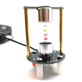
Push-down magnetische levitatie elektronische DIY reserveonderdelen soldeertraining DIY-kit
-
US$3.99
-
US$6.99
DIY Droom Kristal Elektronische Kolomlicht Kubus LED Muziek Stem Spectrum Kit
-
US$13.99
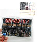
Geekcreit® DS3231 Hoog-nauwkeurige Multifunctionele LED Dot Matrix Animatie-effecten Klok DIY Kit
-
US$6.99
Elektromagnetisch geweer DIY-kit Elektromagnetisch experimenteermateriaal
-
US$18.51
-
US$8.99
DIY 51 Enkelvoudige Chip Microcomputer Elektronische Weegschaal Productie Kit
-
US$9.99
DC12V DIY Elektronica Kit Ultrasoon Suspensie Staande Golf Controller Diy Las Kit
-
US$9.99
-
US$4.99
DIY Ultrasone Ophanging Leerkit Mini Levitator Set 12V Niet Gemonteerd
-
US$2.99
-
US$5.99
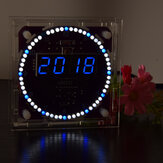
DIY LED Digitaal Horloge Elektronische Klok Kit Met Transparante Cover
-
US$2.99
DC5V-9V LED Chaserr DIY Kit LED Tracking Light DIY Onderdelen Elektronische Productie Kit
-
US$4.99
Geekcreit® DIY Trillende LED Dobbelsteen Kit Met Kleine Trilmotor
-
US$1.99
-
US$39.99
-
US$12.99
-
US$2.99
-
US$9.99
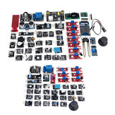
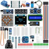
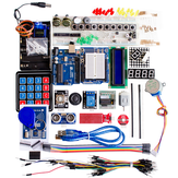
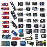
45 IN 1/37 IN 1 Sensor Module Startersets Set Voor Arduino Raspberry Pi Onderwijs Tas Pakket
-
US$2.59
C51 4 Bits Elektronische Klok Elektronische Productie Set DIY Kits
-
US$9.99
-
US$9.99
-
US$10.99
-
US$5.99
-
US$2.99
EQKIT® Arc Ontstekingsaansteker DC3-5V 3A DIY Hoogspanningselektronische Aansteker Module Kit
-
US$14.99
-
US$8.99
-
US$11.99
-
US$29.99
-
US$7.99
-
US$4.99
EQKIT® DIY FLA-1 Eenvoudige Zaklamp Circuit Board Elektronische Kit
-
US$4.59
Geekcreit® XR2206 Functiegolfvormgenerator DIY-kit Sinus Driehoek Vierkante Uitgang 1HZ-1MHZ
-
US$1.99
-
US$14.99
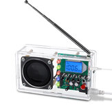
DIY Luchtvaart Band Ontvanger Kit Hoge Gevoeligheid Luchtgolf Ontvanger Klassieke Versie
-
US$11.99
-
US$20.99
-
US$2.40
-
US$3.99
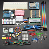
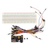
Geekcreit MB-102 MB102 Solderless Broodplank + Voeding + Jumperkabelset
-
US$34.99
-
US$17.99
-
US$3.59
EQKIT® SMD Component Soldeer Oefenbord DIY Elektronische Productie Module Kit
-
US$9.99
-
US$39.56
-
US$4.99
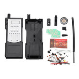
DIY Elektronische Walkie-talkie Productie Kit Startersset Lasexperiment Trainingskit
-
US$16.99
-
US$15.99


recommendation for you
-
US$3.54
-
US$9.99
-
US$4.99
-
US$2.99
-
US$11.99
-
US$1.99
-
US$6.99
-
US$6.99
-
US$22.99
-
US$15.99